


| Quantity: | |
|---|---|
Overview
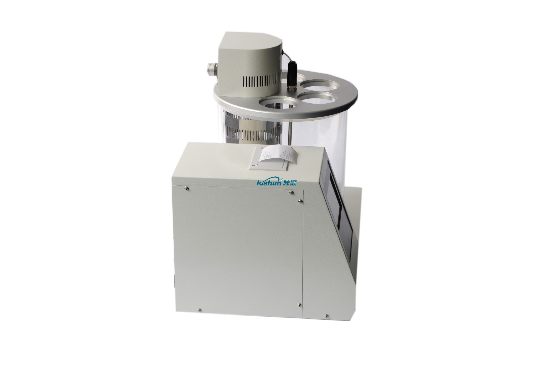
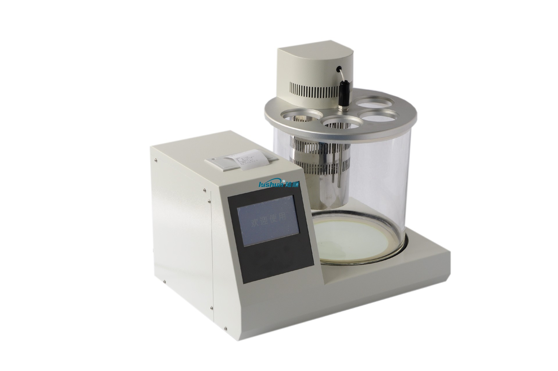
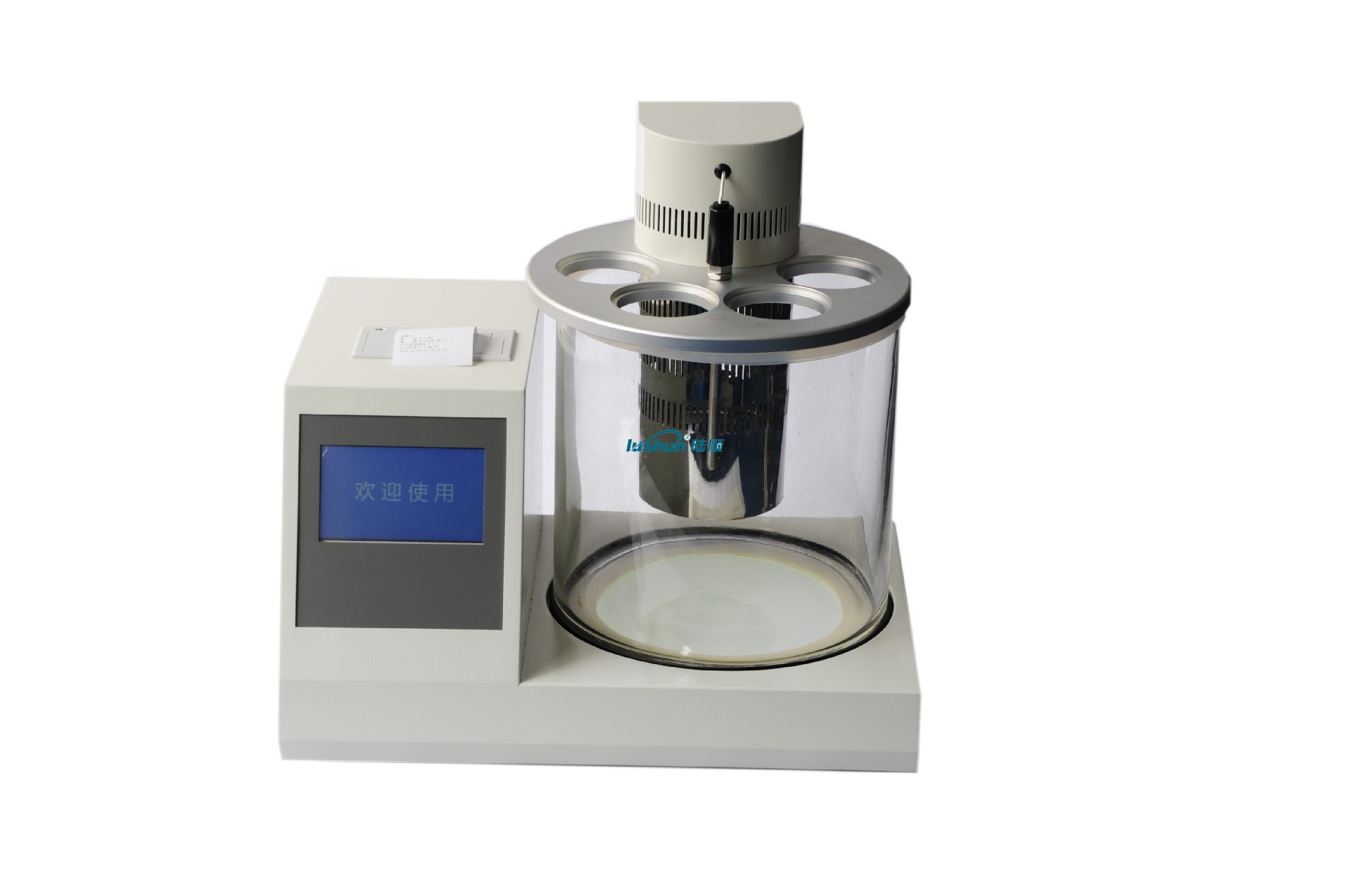
This type of kinematic viscosity automatic measuring instrument complies with GB/T265-1988 "Petroleum Product Kinematic Viscosity Determination Method and Dynamic Viscometer Algorithm", and is suitable for measuring the kinematic viscosity of liquid petroleum products (Newtonian liquids). This method refers to measuring the time for a certain volume of liquid to flow through a calibrated glass capillary viscometer under gravity at a constant temperature. The product of the capillary constant of the viscometer and the flow time is the kinematic viscosity of the measured liquid at that temperature (the product of the kinematic viscosity at that temperature and the density of the liquid at the same temperature is the dynamic viscosity of the liquid at that temperature).
The automatic viscosity tester for petroleum products adopts advanced fuzzy PID temperature control technology, with precise temperature control and an accuracy of ± 0.1 ℃. Multiple temperature control points specified by national standards such as 20 ℃, 40 ℃, 60 ℃, 80 ℃, and 100 ℃ can be set, and any temperature control can be set (the set temperature should be higher than room temperature). It can be used as a regular constant temperature water bath.
The automatic measuring instrument for the kinematic viscosity of petroleum products can simultaneously use four glass capillary viscometers to measure the kinematic viscosity at the same constant temperature. Each viscometer can repeat the measurement four times as a set of test data. The instrument will automatically remove timing results that do not meet the tolerance requirements according to the national standard method, and take the average of several other timing values that meet the tolerance requirements to calculate and obtain the kinematic viscosity value of the test group. When it is not necessary to obtain precise measurement results (often to roughly observe the approximate kinematic viscosity value of an unknown sample), the kinematic viscosity value can be calculated at any time by timing once, twice, or three times. This can obtain the approximate kinematic viscosity value of the tested sample in a shorter time. Afterwards, when the timing is four times, the instrument strictly follows the national standard method requirements to accurately obtain the final kinematic viscosity value of the tested sample.
Petroleum product kinematic viscosity automatic measuring instrument, using high-definition color touch screen technology, with rich and clear interface content, fast and flexible touch screen response; Using a panel mounted thermal printer, the measurement is completed and the measurement results, sample number, measurement time, kinematic viscosity value, and other information are automatically and quickly printed.
Technical Parameter
Display: Color LCD display+touch screen
Temperature control range: room temperature~150 ℃
Set temperature: 20 ℃, 40 ℃, 50 ℃, 80 ℃, 100 ℃, any value (above room temperature~150 ℃)
Temperature control accuracy: ± 0.1 ℃
Test holes: 4 holes
Timing range: 0~999 seconds (according to national standards, the flow time of each test sample must be greater than 200 seconds)
Timing accuracy: 0.1 seconds
Timing times: 1-4 times optional
Printing method: Panel mounted thermal printer
Power supply: AC220V ± 5% 50Hz ± 5%
Power: 1500W
Operating environment temperature: 5 ℃~35 ℃
Operating environment humidity: 10%~80%
VRP Series Varnish Removal Oil Purifier
Application
Used in gas and steam turbine, compressor, to remove dissolved and suspended soft pollutants in oil products, sludge and other harmful substances. Avoid turbine failures and expensive oil changes due to paint film problems. When the film is formed, the loss of production is very high. The initial formation of the film is known as a soft pollutant, caused by hot spots in the system, such as bearings, pumps, and high flow on-line filtration. Recent studies have found that the existence of soft pollutants can be divided into dissolved state and suspended state, by removing these soft oxides can avoid the production of paint film. Once the film forms, it will clog valves, filters and other small links, and the life of the oil will be significantly reduced.
The formation of cleaning film will cause the following adverse consequences: valve adhesion, loss of control, resulting in unit failure or startup failure; Filter plugging, limiting oil flow, resulting in oil temperature rise and wear increase; Heat exchange failure, oil temperature rise; Sandpaper surface, increase component wear; Forming paint on the bearing, limiting flow, increasing wear and temperature; Frequent oil changes and system flushes. When the soft pollutants are dissolved in the oil, typically when the oil temperature is above 40℃, they cannot be removed by ordinary mechanical filtration or electrostatic filtration, and these soft pollutants show natural magnetism. For polar absorption, the cooler metal surface "cold spot", i.e. the valve and cooler. When the temperature of the oil is lowered, the thermal stability of the soft pollutants is less than that of the oil, so they are more likely to bake hard on hot surfaces, such as axial shafts.
VRP paint film cleaner. It achieves revolutionary and efficient removal of soft pollutants (dissolved and suspended) from oil products, including gas and steam turbines and compressors under high temperature operation. The warm oil is pumped from the lowest point at the bottom of the tank to the VRP paint film purifier by the equipment's own transfer pump. After cooling treatment (using the thermal stability of the paint film is worse than that of oil), the paint film, particulate matter and moisture are removed by the filter element with wood fiber as the raw material (no need to use ion-exchange resin filter material, greatly saving the cost of use).
Features:
● Increase system reliability and stability. ● No more shutdowns and startup failures caused by paint film.
● No longer need to clean the tank and system flushing. ● Increase jacking oil pressure, more stable bearing temperature.
● Improve the life of oil products, blood additives and system components, such as bearings, valves, seals, etc.
● Great savings can be achieved by avoiding turbine failure and extending the life of oil products. Features:
● Increase system reliability and stability. ● No more shutdowns and startup failures caused by paint film.
● No longer need to clean the tank and system flushing. ● Increase jacking oil pressure, more stable bearing temperature.
● Improve the life of oil products, blood additives and system components, such as bearings, valves, seals, etc.
● Great savings can be achieved by avoiding turbine failure and extending the life of oil products.
Technical Specification
|
Model |
VRP-10 |
|
Flow |
10L/min |
|
Working Pressure |
≤0.5Mpa |
|
Total Power |
5.55KW |
|
Power Supply |
AC380V/50Hz |
|
Overall Dimension |
1466mm×1126mm×1750mm |
|
Net Weight |
500kg |
|
Particle contamination degree(NAS1638)
|
≤6grade |
|
MPC data |
<15 |
■Above size and weight of this equipment are for reference only, the specific data shall be subject to its physical object.


 渝公网安备 50010702502819号