


| Quantity: | |
|---|---|
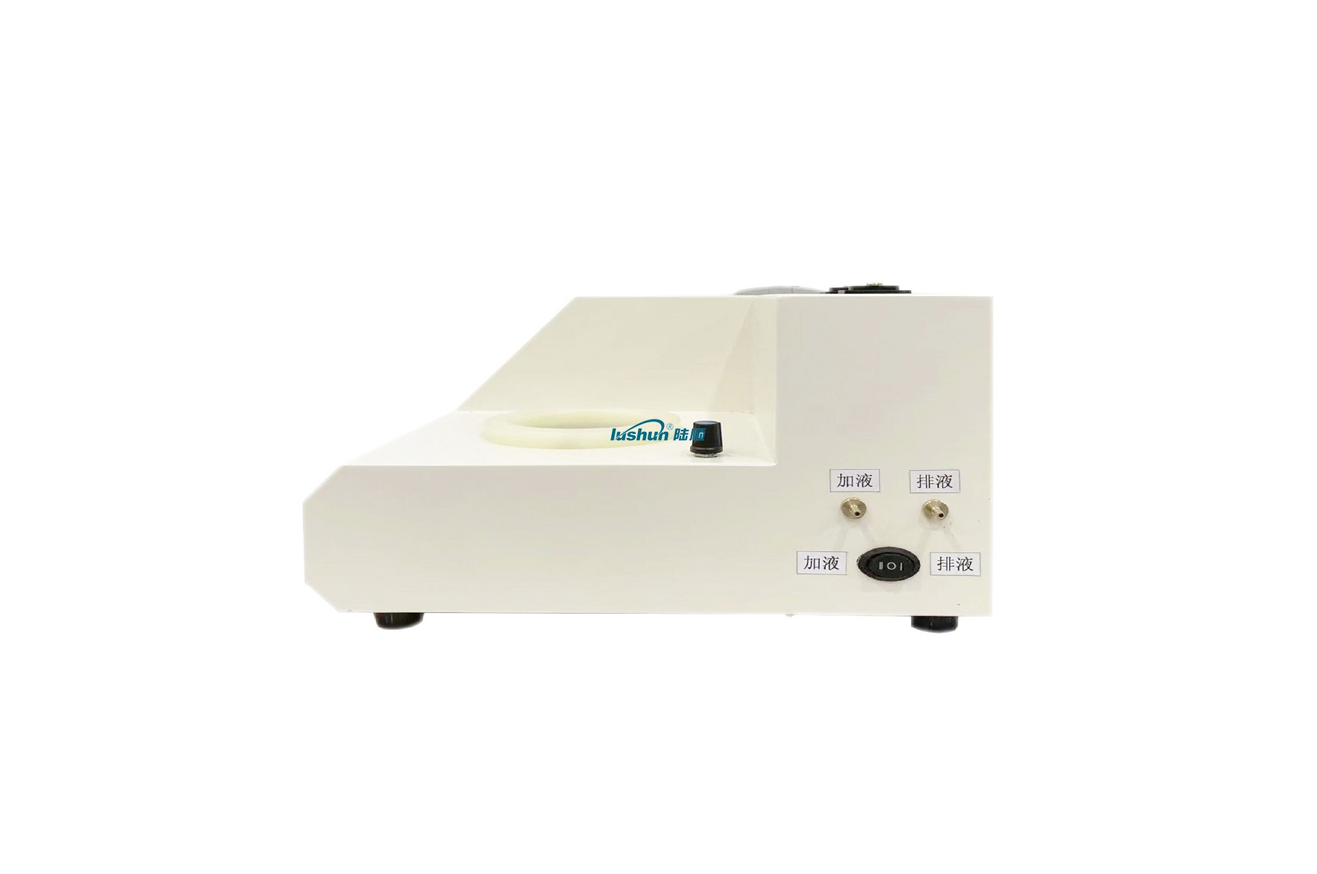
Overview
This type of trace moisture analyzer is based on the GB/T 7600 standard and uses the Karl Fischer titration method to determine the trace moisture of different substances, which is the most reliable method. The micro moisture analyzer has successfully applied this method, using the most advanced automatic control circuit, a 32-bit embedded microprocessor as the main control core, and embedded in a mini operating system. This makes the instrument more reliable and convenient to use. It has the characteristics of fast analysis speed, simple operation, high accuracy, and strong automation. Widely used in sectors such as petroleum, chemical, power, railway, pesticide, medicine, and environmental protection.
Instrument features:
Adopting a 32-bit embedded microprocessor as the main control core, embedded with a mini operating system.
·0-400mA automatic detection, high accuracy, fast measurement speed, stable and reliable.
·The motherboard adopts high-quality surface mount components, with high integration, simple operation, and long lifespan
·It contains 4 calculation formulas, and the measurement results are automatically converted to the required units and can be converted to each other.
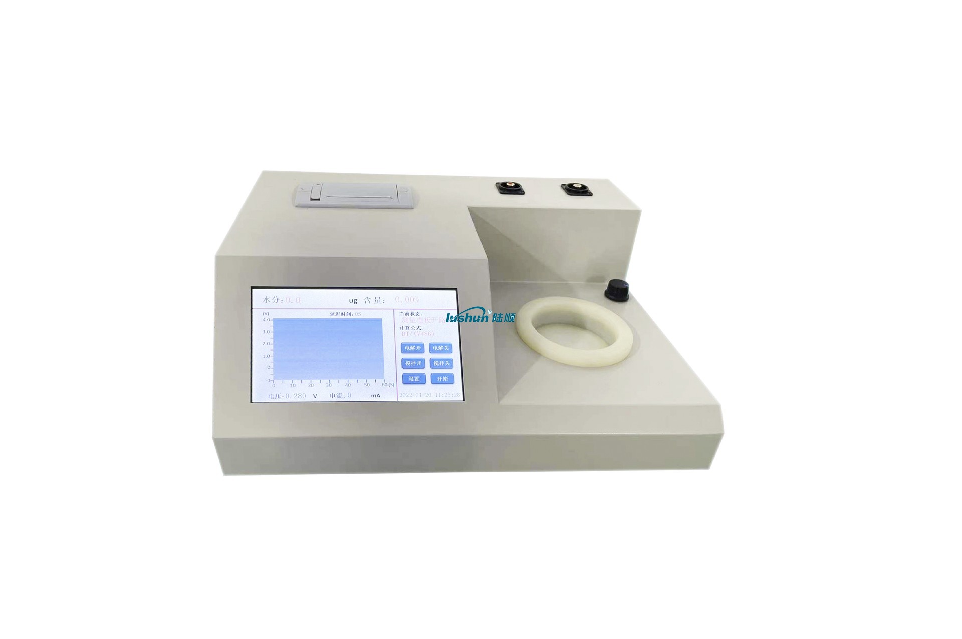
·Large color touch screen, full numeric keyboard, simpler operation, convenient and fast data calculation.
·Having graph curve analysis to assist in analyzing moisture content trends.
·Switch between Chinese and English at any time.
Technical Parameter
Titration method: Electric titration (Coulomb analysis)
Display: Color LCD touch screen
Electrolytic current control: 0-400mA automatic control
Measurement range: 1ug~200mg
Sensitive valve: 0.1 µ g H2O
Accuracy: 10 µ g to 1000 µ g ± 10%
Printer: Micro thermal printer
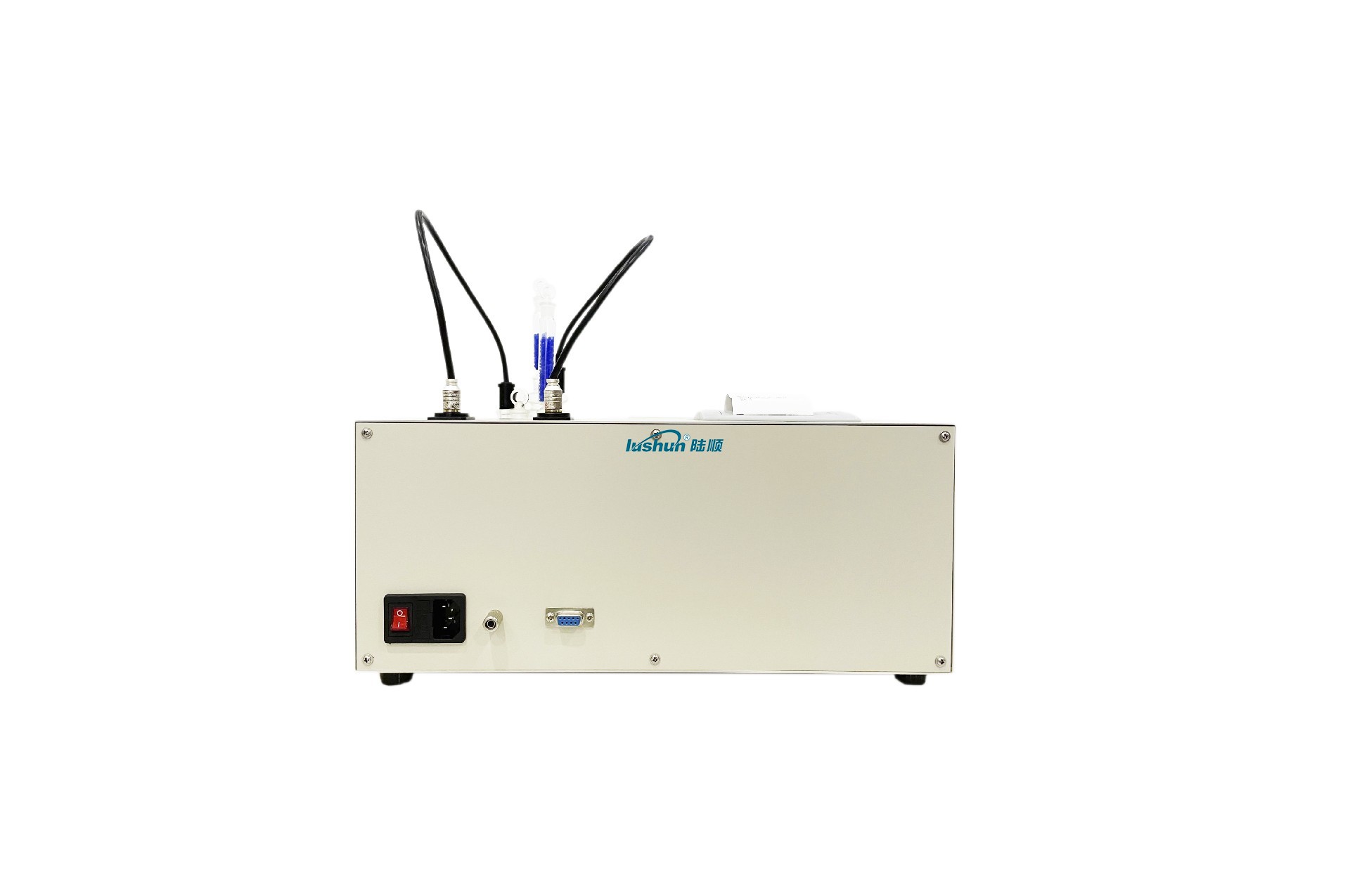
Power supply: 220V ± 10%, 50Hz
Power: < 40W
Operating environment temperature: 5-40 ℃
Usage environment humidity: ≤ 85%
Dimensions: 380 × 310 × 180 MM
Weight: Approximately 6kg
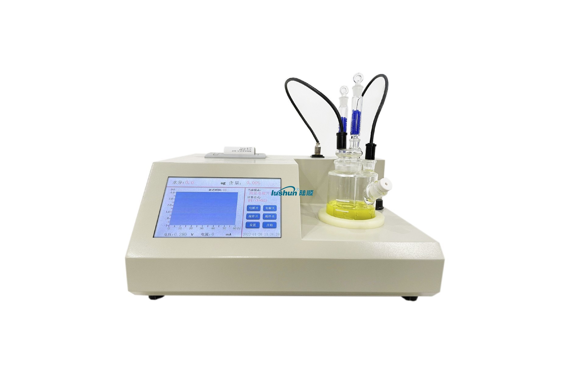
Working principle
The reaction equation between Karl Fischer reagent and water is:
I2 + SO2 + 3C5 H5 N + H2O—→2C5 H5 N•HI + C5 H5 N•SO3 …… (1)
C5 H5 N•SO3 + CH3OH—→C5 H5 N•HSO4CH3 ………………… (2)
The reagent solution used is a mixture of dominant iodine and arsenic, methanol, etc. filled with sulfur dioxide. Iodine is formed on the anode through electrolysis, and the generated iodine is directly proportional to the amount of charge according to Faraday's law. The following formula:
2I¯+ 2e —→ I2 ……………………………………… (3)
From equation (1), it can be seen that the number of moles of iodine participating in the reaction is equal to the number of moles of water. Inject the sample into the electrolyte, and the water in the sample participates in the reaction. The instrument can reflect the consumption of iodine during the reaction process, and the consumption of iodine can be calculated based on the amount of electricity required to electrolyze the same amount of iodine. After calculation by the instrument, the measured water content can be directly displayed on the liquid crystal display. The instrument adopts an electrolytic current automatic control system, and the magnitude of the electrolytic current can be automatically controlled according to the moisture content in the sample, with a maximum of 400mA. During the electrolysis process, the moisture gradually decreases, and the electrolysis rate decreases proportionally until the control circuit at the end of electrolysis is activated. This system ensures high precision, high sensitivity valves, and high speed during the analysis process. In addition, during the measurement process, it is inevitable to introduce some interfering factors, such as moisture invading from the air, causing the electrolytic cell to absorb moisture and generate blank current. However, as the instrument has the function of storing blank current, the number displayed on the screen is the true water content in the tested sample.
VRP Series Varnish Removal Oil Purifier
Application
Used in gas and steam turbine, compressor, to remove dissolved and suspended soft pollutants in oil products, sludge and other harmful substances. Avoid turbine failures and expensive oil changes due to paint film problems. When the film is formed, the loss of production is very high. The initial formation of the film is known as a soft pollutant, caused by hot spots in the system, such as bearings, pumps, and high flow on-line filtration. Recent studies have found that the existence of soft pollutants can be divided into dissolved state and suspended state, by removing these soft oxides can avoid the production of paint film. Once the film forms, it will clog valves, filters and other small links, and the life of the oil will be significantly reduced.
The formation of cleaning film will cause the following adverse consequences: valve adhesion, loss of control, resulting in unit failure or startup failure; Filter plugging, limiting oil flow, resulting in oil temperature rise and wear increase; Heat exchange failure, oil temperature rise; Sandpaper surface, increase component wear; Forming paint on the bearing, limiting flow, increasing wear and temperature; Frequent oil changes and system flushes. When the soft pollutants are dissolved in the oil, typically when the oil temperature is above 40℃, they cannot be removed by ordinary mechanical filtration or electrostatic filtration, and these soft pollutants show natural magnetism. For polar absorption, the cooler metal surface "cold spot", i.e. the valve and cooler. When the temperature of the oil is lowered, the thermal stability of the soft pollutants is less than that of the oil, so they are more likely to bake hard on hot surfaces, such as axial shafts.
VRP paint film cleaner. It achieves revolutionary and efficient removal of soft pollutants (dissolved and suspended) from oil products, including gas and steam turbines and compressors under high temperature operation. The warm oil is pumped from the lowest point at the bottom of the tank to the VRP paint film purifier by the equipment's own transfer pump. After cooling treatment (using the thermal stability of the paint film is worse than that of oil), the paint film, particulate matter and moisture are removed by the filter element with wood fiber as the raw material (no need to use ion-exchange resin filter material, greatly saving the cost of use).
Features:
● Increase system reliability and stability. ● No more shutdowns and startup failures caused by paint film.
● No longer need to clean the tank and system flushing. ● Increase jacking oil pressure, more stable bearing temperature.
● Improve the life of oil products, blood additives and system components, such as bearings, valves, seals, etc.
● Great savings can be achieved by avoiding turbine failure and extending the life of oil products. Features:
● Increase system reliability and stability. ● No more shutdowns and startup failures caused by paint film.
● No longer need to clean the tank and system flushing. ● Increase jacking oil pressure, more stable bearing temperature.
● Improve the life of oil products, blood additives and system components, such as bearings, valves, seals, etc.
● Great savings can be achieved by avoiding turbine failure and extending the life of oil products.
Technical Specification
|
Model |
VRP-10 |
|
Flow |
10L/min |
|
Working Pressure |
≤0.5Mpa |
|
Total Power |
5.55KW |
|
Power Supply |
AC380V/50Hz |
|
Overall Dimension |
1466mm×1126mm×1750mm |
|
Net Weight |
500kg |
|
Particle contamination degree(NAS1638)
|
≤6grade |
|
MPC data |
<15 |
■Above size and weight of this equipment are for reference only, the specific data shall be subject to its physical object.


 渝公网安备 50010702502819号