


| Quantity: | |
|---|---|
Overview
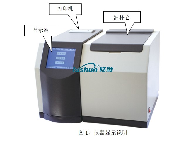
The oil dielectric loss and resistivity tester is designed and manufactured in accordance with GB/T5564-2007 "Measurement of relative permittivity, dielectric loss factor, and DC resistivity of liquid insulation materials". Used for measuring the dielectric loss factor and DC resistivity of liquid insulation media such as insulating oil. Integrated structure. Internally integrated with main components such as dielectric loss oil cup, temperature controller, temperature sensor, dielectric loss testing bridge, AC test power supply, standard capacitor, high resistance meter, DC high voltage source, etc. The instrument adopts fully digital technology internally, with intelligent and automated measurement. It is equipped with a large screen 5.7-inch TFT pure color LCD touch display, a full Chinese menu, and test results can be automatically stored and printed out. Operators can proficiently use it without professional training.
Main Function And Features
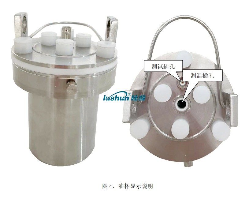
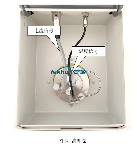
(1) The oil cup adopts a three electrode structure that complies with the national standard GB/T5564-2007, with a spacing of 2mm between electrodes, which can eliminate the influence of stray capacitance and leakage on the dielectric loss test results.
(2) The instrument adopts medium frequency induction heating and PID temperature control algorithm. This heating method has the advantages of non-contact between the oil cup and the heating element, uniform heating, fast speed, and easy control, which strictly controls the temperature within the preset temperature error range.
(3) The internal standard capacitor is an SF6 gas filled three-point polar capacitor, whose dielectric loss and capacitance are not affected by environmental temperature, humidity, etc., ensuring the accuracy of the instrument even after long-term use.
(4) Complete protection function. When there is overvoltage, overcurrent, or high-voltage short circuit, the instrument can quickly cut off the high voltage and issue a warning message. When the temperature sensor fails or is not connected, a warning message is issued. A temperature limiting relay is installed inside the medium frequency induction heating furnace. When the temperature exceeds 120 degrees, the relay is released and the heating stops.
(5) Convenient setting of experimental parameters. The temperature setting range is 40-120 ℃, the AC voltage setting range is 200-2200V, and the DC voltage setting range is 200-500V.
(6) Adopting a large screen TFT pure color LCD touch display, the display is clear. With simple setup, the instrument can automatically perform testing. And automatically store and print test results.
(7) Equipped with a real-time clock, the test date and time can be saved, displayed, and printed along with the test results.
(8) Empty electrode cup calibration function. Measure the capacitance and dielectric loss factor of the empty electrode cup to determine its cleaning and assembly condition. Calibration data is automatically saved for accurate calculation of relative permittivity and DC resistivity.
(9) The instrument is based on the RAM9 platform, with high testing accuracy and fast speed.
Specification
Power supply voltage: AC 220V±10%
Power frequency: 50Hz/60Hz ±1%
Measurement range: capacitance 5pF~200pF
Relative permittivity 1.000~30.000
Dielectric loss factor 0.00001~100
DC resistivity ranging from 2.5 M Ω m to 20 T Ω m
Measurement accuracy: relative permittivity ± (1-10)% reading
Dielectric loss factor ± (5% reading ± 0.0002)
DC resistivity ± 10% reading
Resolution: capacitance of 0.01pF
Relative permittivity 0.001
Dielectric loss factor 0.00001
Temperature measurement range: 40~120℃
Temperature measurement error: ±0.5℃
Communication experiment voltage: 200-2200V continuously adjustable, frequency 50Hz
DC test voltage: 0-500V continuously adjustable
Power consumption: 500W
External dimensions: 460mm× 370mm×330mm
Total weight: 25Kg
Conditions of Use
Environmental temperature: 0℃~40℃
Relative humidity:<75%
Image caption:
VRP Series Varnish Removal Oil Purifier
Application
Used in gas and steam turbine, compressor, to remove dissolved and suspended soft pollutants in oil products, sludge and other harmful substances. Avoid turbine failures and expensive oil changes due to paint film problems. When the film is formed, the loss of production is very high. The initial formation of the film is known as a soft pollutant, caused by hot spots in the system, such as bearings, pumps, and high flow on-line filtration. Recent studies have found that the existence of soft pollutants can be divided into dissolved state and suspended state, by removing these soft oxides can avoid the production of paint film. Once the film forms, it will clog valves, filters and other small links, and the life of the oil will be significantly reduced.
The formation of cleaning film will cause the following adverse consequences: valve adhesion, loss of control, resulting in unit failure or startup failure; Filter plugging, limiting oil flow, resulting in oil temperature rise and wear increase; Heat exchange failure, oil temperature rise; Sandpaper surface, increase component wear; Forming paint on the bearing, limiting flow, increasing wear and temperature; Frequent oil changes and system flushes. When the soft pollutants are dissolved in the oil, typically when the oil temperature is above 40℃, they cannot be removed by ordinary mechanical filtration or electrostatic filtration, and these soft pollutants show natural magnetism. For polar absorption, the cooler metal surface "cold spot", i.e. the valve and cooler. When the temperature of the oil is lowered, the thermal stability of the soft pollutants is less than that of the oil, so they are more likely to bake hard on hot surfaces, such as axial shafts.
VRP paint film cleaner. It achieves revolutionary and efficient removal of soft pollutants (dissolved and suspended) from oil products, including gas and steam turbines and compressors under high temperature operation. The warm oil is pumped from the lowest point at the bottom of the tank to the VRP paint film purifier by the equipment's own transfer pump. After cooling treatment (using the thermal stability of the paint film is worse than that of oil), the paint film, particulate matter and moisture are removed by the filter element with wood fiber as the raw material (no need to use ion-exchange resin filter material, greatly saving the cost of use).
Features:
● Increase system reliability and stability. ● No more shutdowns and startup failures caused by paint film.
● No longer need to clean the tank and system flushing. ● Increase jacking oil pressure, more stable bearing temperature.
● Improve the life of oil products, blood additives and system components, such as bearings, valves, seals, etc.
● Great savings can be achieved by avoiding turbine failure and extending the life of oil products. Features:
● Increase system reliability and stability. ● No more shutdowns and startup failures caused by paint film.
● No longer need to clean the tank and system flushing. ● Increase jacking oil pressure, more stable bearing temperature.
● Improve the life of oil products, blood additives and system components, such as bearings, valves, seals, etc.
● Great savings can be achieved by avoiding turbine failure and extending the life of oil products.
Technical Specification
|
Model |
VRP-10 |
|
Flow |
10L/min |
|
Working Pressure |
≤0.5Mpa |
|
Total Power |
5.55KW |
|
Power Supply |
AC380V/50Hz |
|
Overall Dimension |
1466mm×1126mm×1750mm |
|
Net Weight |
500kg |
|
Particle contamination degree(NAS1638)
|
≤6grade |
|
MPC data |
<15 |
■Above size and weight of this equipment are for reference only, the specific data shall be subject to its physical object.


 渝公网安备 50010702502819号