


| Quantity: | |
|---|---|
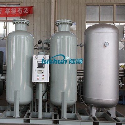
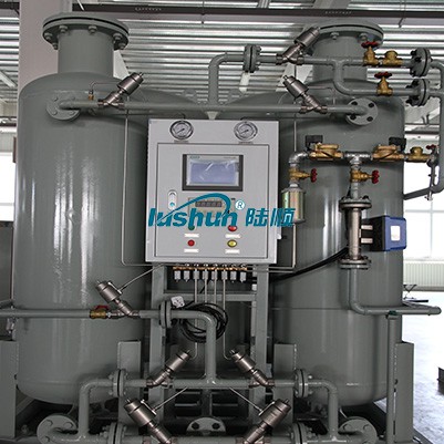
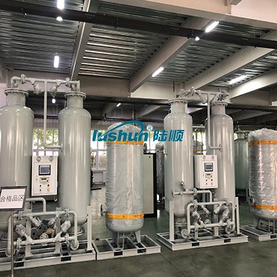
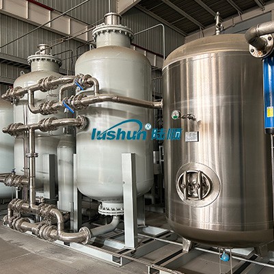
Nitrogen Generator
Principle of nitrogen production by pressure swing adsorption air separation
The main components in the air are nitrogen and oxygen, so the adsorbent with different adsorption selectivity for nitrogen and oxygen can be selected, and the appropriate process can be designed to separate nitrogen and oxygen to produce nitrogen.
Both nitrogen and oxygen have quadrupole moments, but the quadrupole moment of nitrogen (0.31A) is much larger than that of oxygen (0.10A), and under a certain pressure, the ability of oxygen to be adsorbed in carbon molecular sieve is much stronger than nitrogen (the force of oxygen and the surface ions of the molecular sieve is strong, as shown in Figure 1). Therefore, when the air passes through the adsorption bed equipped with carbon molecular sieve adsorbent under pressure, oxygen is adsorbed by the molecular sieve, and nitrogen is enriched in the gas phase due to less adsorption and flows out of the adsorption bed, so that oxygen and nitrogen are separated to obtain oxygen. When the molecular sieve adsorbs oxygen to near saturation, the air is stopped and the pressure of the adsorption bed is reduced, the oxygen adsorbed by the molecular sieve can be desorbed, and the molecular sieve can be regenerated and reused. Two or more adsorption beds can be switched in turn to produce nitrogen continuously. As shown below, A is oxygen and B is nitrogen.
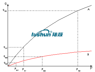
schematic diagram
Nitrogen production system process flow introduction
Air compressor system: First, the first step of raw air compression by the compressor to ≥0.8-1.0Mpa (gauge pressure, stable value),Exhaust temperature ≤45℃, exhaust oil content ≤3PPm, exhaust dust content ≤3μm.
Air buffer system: compressed air first into the air buffer tank, initial cooling drainage, stable output pressure.
Compressed air purification system: After the compressed air comes out of the air buffer tank, it is first passed through the efficient oil remover and frozen
Type dryer, adsorption dryer, supervisor passing filter, oil mist filter, dust filter, super
Air purification equipment such as high-efficiency micro-oil mist filters remove oil, water and dust in the compressed air to make the compressed air
Gas pressure dew point reaches 2-10℃, oil content ≤0.003PPm, temperature ≤38℃, dust filter diameter ≤0.01um. The purified compressed air enters the air process tank.
PSA nitrogen production and filtration system: Clean compressed air from the air process tank is fed into two fills for adsorption agent (composite bed structure) pressure swing adsorption separation system, clean compressed air from the bottom of the adsorption tower into the gas after diffusing through a special air diffuser, it uniformly enters the adsorption tower for oxygen and nitrogen adsorption separation, and then from nitrogen flows out of the outlet, enters the nitrogen buffer tank, and is filtered again by the nitrogen filter to complete the nitrogen production process then, after pressure equalization and decompression (to normal pressure), the adsorbent desorbs the adsorbed impurity components (mainly O2 and a small amount of CO2, H2O) to complete the regeneration of the adsorbent. The two adsorption towers operate alternately and continuously feed into the original feed air, continuous production indicators to meet the production needs of nitrogen.
Nitrogen production equipment standard features:
On-line monitoring of nitrogen purity, flow and pressure.
Programmable valve switching is automatically controlled by a programmable controller.
Failed nitrogen alarm automatic shutdown function for a long time.
Automatic compression of molecular sieve, sinking alarm and limit shutdown protection.
Automatic filter blowdown.
Unqualified nitrogen sound and light alarm and automatic discharge.
Touch screen human-machine interface.
Reserve RS485 communication ports.
Equipment technical characteristics
After more than 20 years of technology accumulation and market application, adhere to research and development and innovation, always maintain the leading core technology, and strive to provide users with the best gas solutions.
The system operating environment is low or normal pressure, safe and convenient.
The equipment has the advantages of simple structure, easy maintenance and low operating cost.
PLC control, automatic unmanned operation.
The purity of nitrogen can be produced at one time by the equipment 99.999%, the purity of nitrogen can be adjusted with the change of flow rate.
R & D team has carried out strict tests on adsorbents to maximize the utilization efficiency of adsorbents and extreme energy saving. The gas consumption of the equipment is only 70% of the industry average.
The most comprehensive and strict adsorbent protection technology, constantly optimize the system process, to ensure the maximum stability of equipment.
The most advanced control system, PC level operation, to achieve full automation of system equipment, process monitoring, remote local switching, pressure start and stop control, instrument and sensor calibration, energy saving load adaptation and many other practical functions.
The system has reasonable design, compact structure and minimum floor area.
The device starts quickly and can supply gas after 30 minutes of boot.
According to the project situation to provide personalized, customized design scheme to meet the actual needs of customers.
VRP Series Varnish Removal Oil Purifier
Application
Used in gas and steam turbine, compressor, to remove dissolved and suspended soft pollutants in oil products, sludge and other harmful substances. Avoid turbine failures and expensive oil changes due to paint film problems. When the film is formed, the loss of production is very high. The initial formation of the film is known as a soft pollutant, caused by hot spots in the system, such as bearings, pumps, and high flow on-line filtration. Recent studies have found that the existence of soft pollutants can be divided into dissolved state and suspended state, by removing these soft oxides can avoid the production of paint film. Once the film forms, it will clog valves, filters and other small links, and the life of the oil will be significantly reduced.
The formation of cleaning film will cause the following adverse consequences: valve adhesion, loss of control, resulting in unit failure or startup failure; Filter plugging, limiting oil flow, resulting in oil temperature rise and wear increase; Heat exchange failure, oil temperature rise; Sandpaper surface, increase component wear; Forming paint on the bearing, limiting flow, increasing wear and temperature; Frequent oil changes and system flushes. When the soft pollutants are dissolved in the oil, typically when the oil temperature is above 40℃, they cannot be removed by ordinary mechanical filtration or electrostatic filtration, and these soft pollutants show natural magnetism. For polar absorption, the cooler metal surface "cold spot", i.e. the valve and cooler. When the temperature of the oil is lowered, the thermal stability of the soft pollutants is less than that of the oil, so they are more likely to bake hard on hot surfaces, such as axial shafts.
VRP paint film cleaner. It achieves revolutionary and efficient removal of soft pollutants (dissolved and suspended) from oil products, including gas and steam turbines and compressors under high temperature operation. The warm oil is pumped from the lowest point at the bottom of the tank to the VRP paint film purifier by the equipment's own transfer pump. After cooling treatment (using the thermal stability of the paint film is worse than that of oil), the paint film, particulate matter and moisture are removed by the filter element with wood fiber as the raw material (no need to use ion-exchange resin filter material, greatly saving the cost of use).
Features:
● Increase system reliability and stability. ● No more shutdowns and startup failures caused by paint film.
● No longer need to clean the tank and system flushing. ● Increase jacking oil pressure, more stable bearing temperature.
● Improve the life of oil products, blood additives and system components, such as bearings, valves, seals, etc.
● Great savings can be achieved by avoiding turbine failure and extending the life of oil products. Features:
● Increase system reliability and stability. ● No more shutdowns and startup failures caused by paint film.
● No longer need to clean the tank and system flushing. ● Increase jacking oil pressure, more stable bearing temperature.
● Improve the life of oil products, blood additives and system components, such as bearings, valves, seals, etc.
● Great savings can be achieved by avoiding turbine failure and extending the life of oil products.
Technical Specification
|
Model |
VRP-10 |
|
Flow |
10L/min |
|
Working Pressure |
≤0.5Mpa |
|
Total Power |
5.55KW |
|
Power Supply |
AC380V/50Hz |
|
Overall Dimension |
1466mm×1126mm×1750mm |
|
Net Weight |
500kg |
|
Particle contamination degree(NAS1638)
|
≤6grade |
|
MPC data |
<15 |
■Above size and weight of this equipment are for reference only, the specific data shall be subject to its physical object.


 渝公网安备 50010702502819号